Solar Powered Analog Synthezier
Feb 26, 2018 22:38 · 669 words · 4 minutes read

For this assigment for Energy, we are to power computation with solar power. I am collaborating with Fanni Fazakas, and we are going to create a solar powered analog synthesizer. This will take energy from the sun and convert it directly into sound waves via a low-power analog circuit.
Generating Sine, Square, and Triangle Waves
We got a circuit design from Eric Rosenthal that can produce a sine, square and triangle wave:
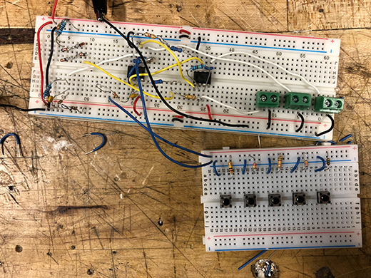
First we wanted to breadboard it to see how it worked. This was super challenging, and took an entire day, but we finally got it to work. In the circuit diagram, there is a 1 Megaohm potentiometer that can modify the frequency of the wave. We replaced it with 5 buttons that each set a discreet resistance in the range of 100k to 1M Ohm:
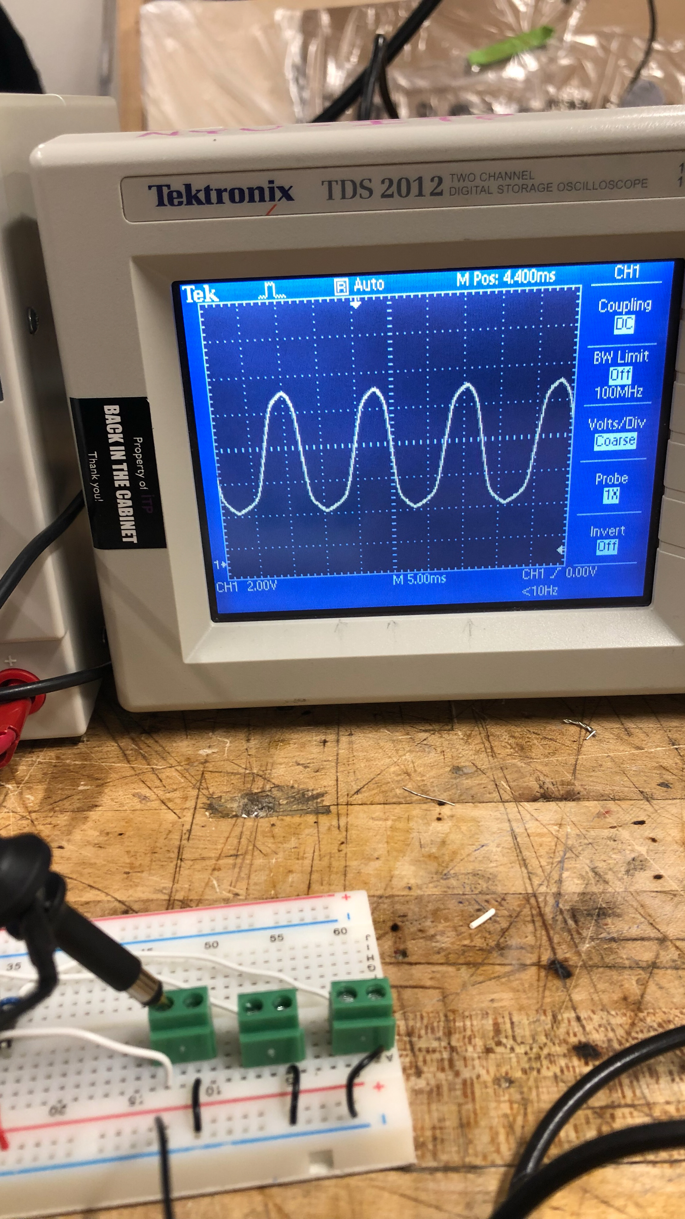
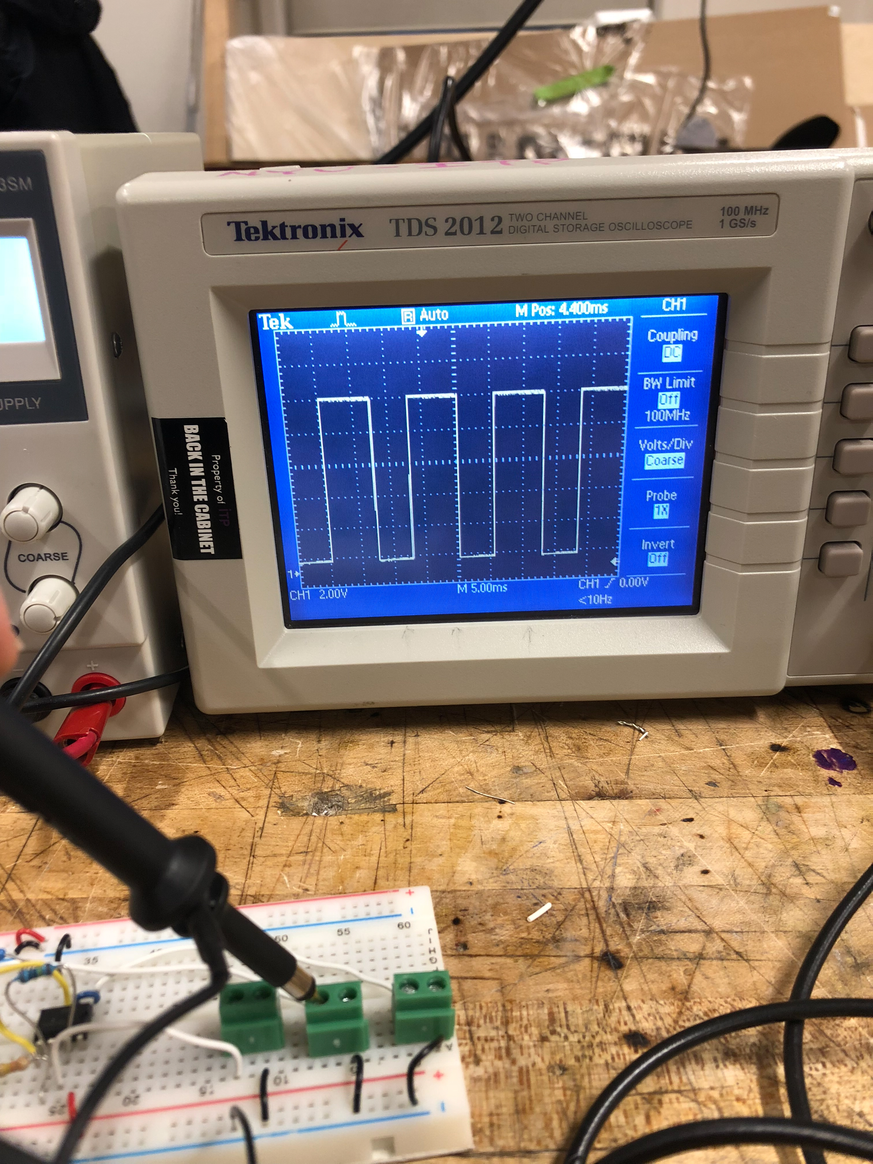
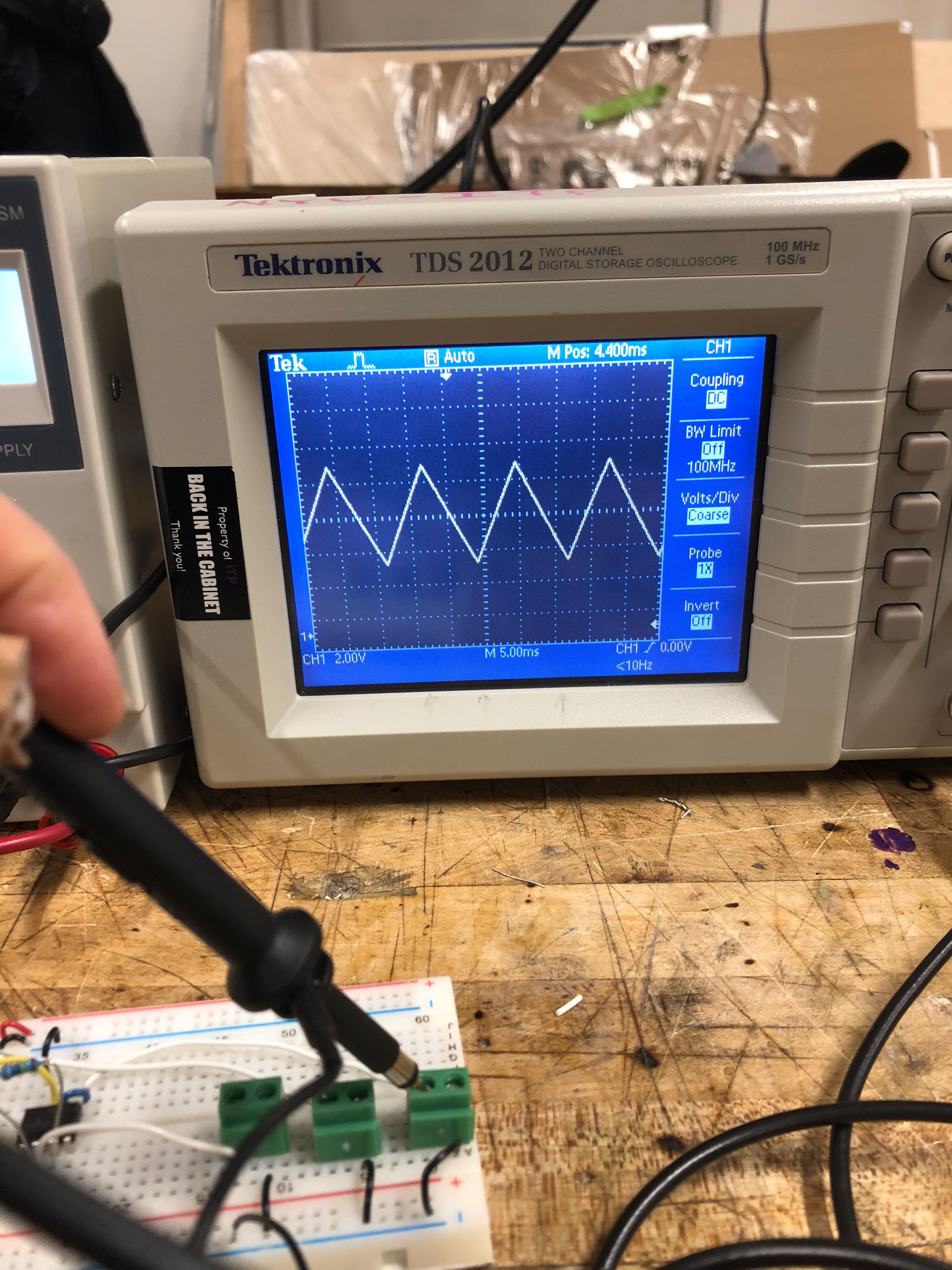
To be honest we don’t understand what the circuit is doing, all we know is how to assemble it and that it works. We tested each wave type with an oscilloscope:
Varying the frequency worked by altering the resistance with each button:
Listening to the Produced Sound
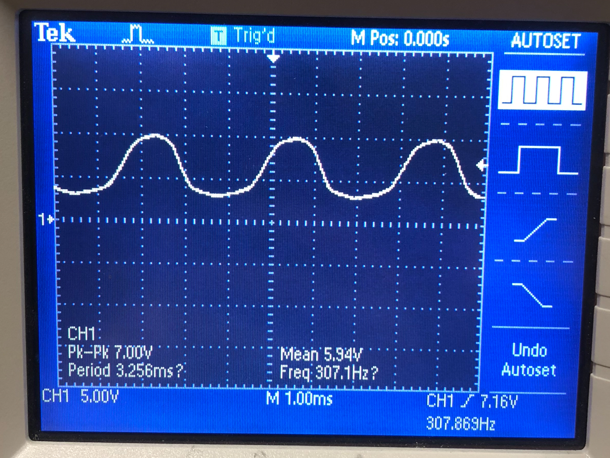
To hear the sounds it generated, we connected headphone via a breadboardable headphone jack. Nothing was audible, however. We asked our friend Amitabh to help us troubleshoot. He showed us on the Oscilloscope how the waves were oscillating above 0, which would prevent the proper vibration from occuring in the headphones for the sound to be audible:
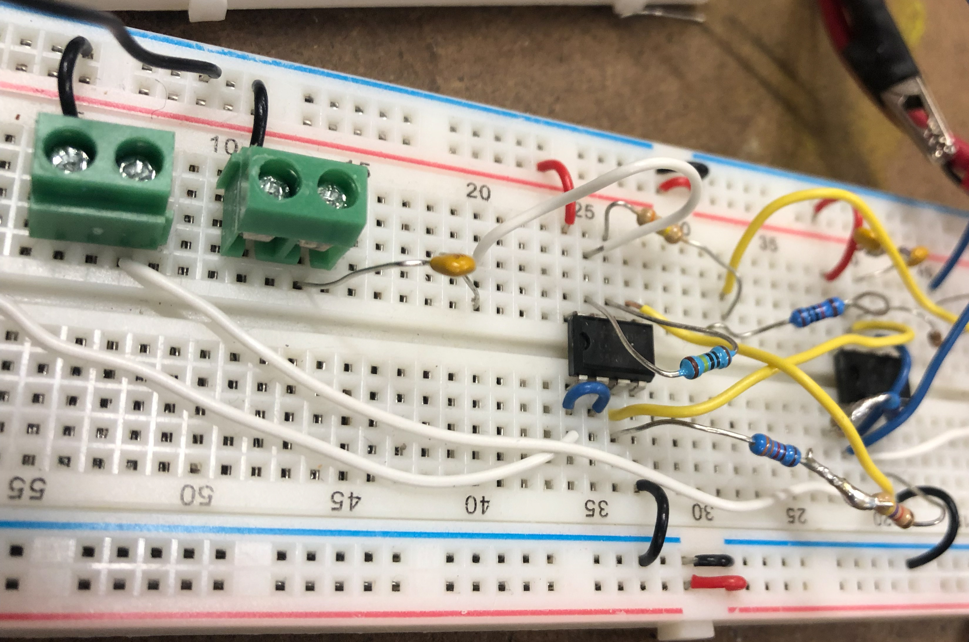
Per his suggestion, we added a 100 nf capacitor to the output:
This smoothed it out and the wave oscillated around 0:
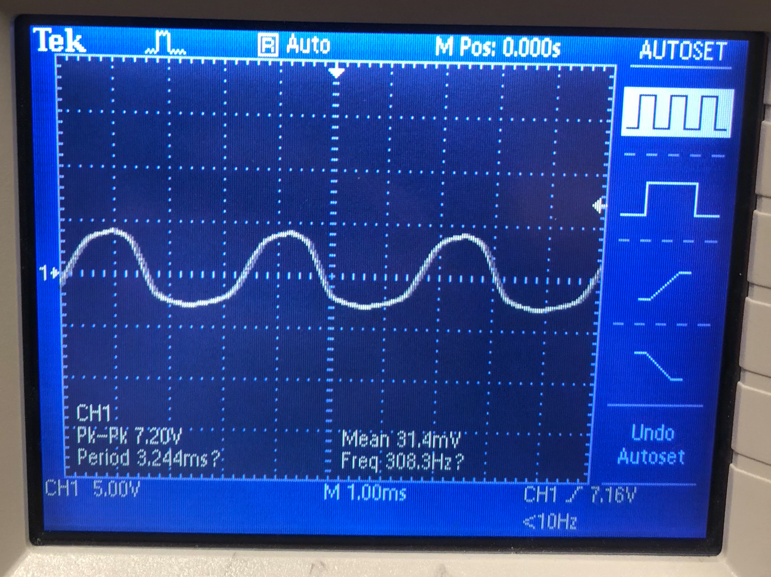
We could successfully now hear sounds tones from the headhpones when listening to sine, square, and triangle waves.
Power Budget
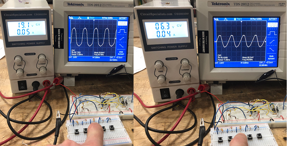
The circuit is designed to work optimally at 12V, and the waves decayed as we lowered the voltage. Around 6v is the minimum voltage. It worked at to 19V, but we didn’t want to turn the voltage up higher for fear of burning something out.
We put a multimeter in series with the power supply’s power and the board. With the headphones and key pressed, and a sound decently audible, the draw was only about 8ma. If we want to connect speakers we would need some sort of an OpAmp.
Assuming that the output wave is 7V as depicted in the oscilloscope, here are a few speakers and what we would need to power them:
| Speaker | Watts | Ohms | Amps at 7V |
|---|---|---|---|
| Adafruit 4 Ohm 3W | 3 | 4 | 0.43 |
| Adafruit 8 Ohm 1W | 1 | 8 | 0.143 |
Since the circuit itself only draws 8 ma, we can leave that out of the total since it’s insegnificant. We would just need more current for the opamps to power the speakers.
Powering it with Solar Energy
For the final step, we wanted to power the circuit with solar energy. We didn’t want to add a battery - the goal of this experiment was to convert solar rays directly into sound, so we would connect solar panels directy to the circuit.
All that was available to check-out from the ITP Equipment Room were 6V solar panels. Since our circuit requires 12V, we checked out two of these and ran then in series:
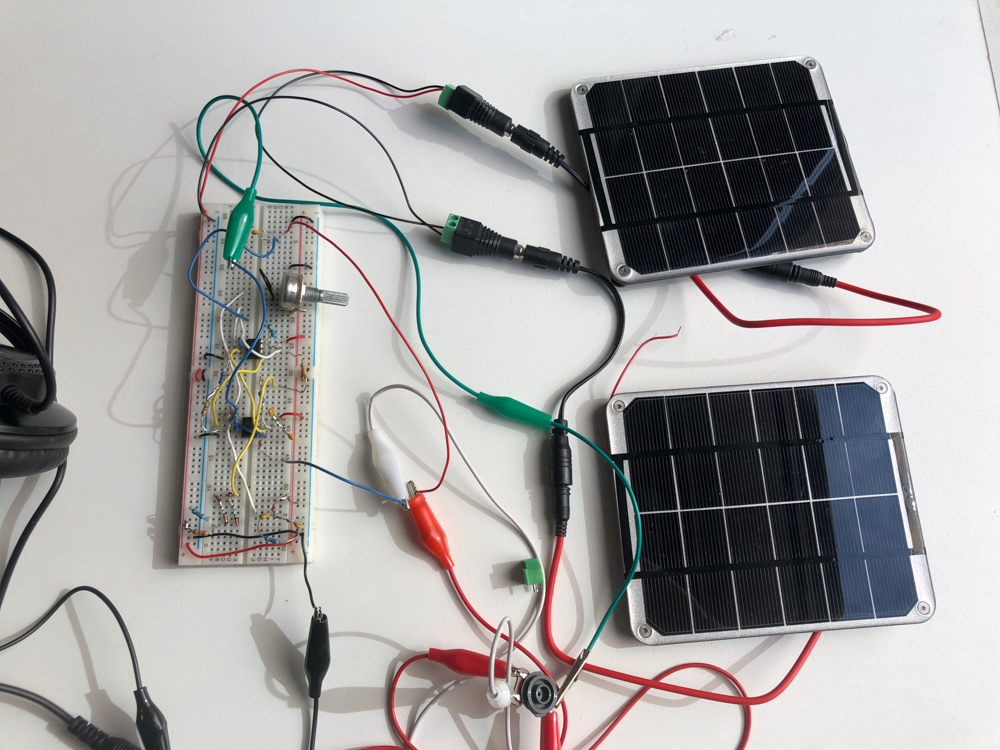
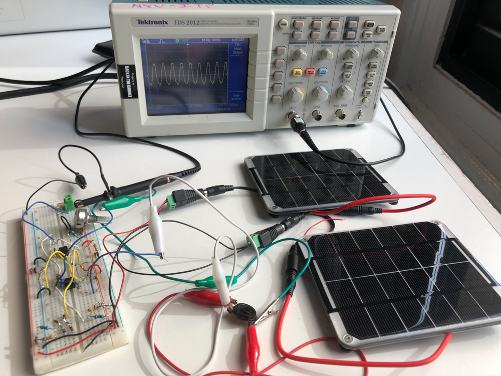
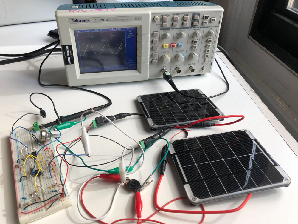
It was able to produce loud sounds through headphones: